Some time ago we published on our website an article related to PLCs, what are PLCs? And what are they used for in the industry? They were some of the questions that we answered in that article. We deal a bit with the subject of programming languages used to program these devices. This time we want to bring you an article that goes a little deeper into this topic, see what differences exist between them, when to use one language or another, in general, go a little deeper into the world of PLC programming languages.
Entering PLC programming.
As you may already know, PLCs are industrial computers, which are used for industrial automation. Like any other computer or smart device, it must be programmed in order to perform the functions for which it was conceived within a certain process. For this, programming languages are used by which engineers program these automata, as these devices are also known.
PLC programming languages are a set of symbols, characters and rules of use that were designed to allow direct communication between specialists and machines. Thanks to this link, we are able to create a program with instructions to control the operation of any process or machinery.
Currently we can group these languages into two categories, visual and written (or graphic and textual). Visuals (graphics) can be classified as high-level languages, while written (textual) as low-level. These languages are specified in the international standard IEC 61131-3. Where all the rules and structures that the PLC programming languages must follow are defined. So, the standard languages that compile directly with the microprocessor are known as low level, they are older and more complex languages and describe all the instructions that you want to execute. Then the high-level ones are the evolution of the previous ones, they are equipped with a graphical interface that facilitates their programming but also limits it to its preset parameters.

Text or Low Level Languages
List of instructions. (IL)
This is one of the oldest languages, it has a high similarity with the Assembler, which is the basis of all the programming languages that exist. The instruction list is often used in medium-small applications due to its structural complexity. It uses command instructions that are directly executed by the processor. To maintain the control and the flow of the program, the jumps and calls to functions (subroutines) are used that allow the execution and taking of actions by the device.

Structured text. (ST)
This is a language more similar to C or Pascal, as it allows the use of more popular instructions such as IF-ELSE to establish conditionals or repeat-until, while-do to execute sequential loops. It is also often used in medium-small applications due to its degree of complexity.
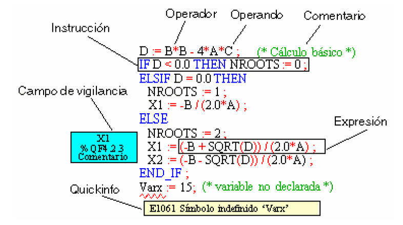
ST programming language.
Graphic or High Level Languages
Sequential Functions Diagram. (SFC)
This language is quite useful for controlling processes that are based on sequential stages. These stages can be actions to execute or transitions through logical conditions. Each stage remains inactive as long as a series of previous stages that lead to its activation have not been completed and activated, or have been activated directly by the programmer in the initial configuration.
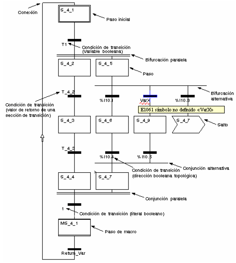
SFC programming language.
Blocks diagram. (FBD)
This language is widely used and one of the favorites by engineers thanks to its similarity to digital electronic circuits and logic gates. The relationship between inputs and outputs is established through the use of function blocks, where each block has a specific purpose or functionality. Said inputs and outputs of the blocks are connected by links which can be used to connect two logic points on the diagram. Either an input variable with an input from the block, an output from a block with an input from another block, or an output from a block with an output variable.
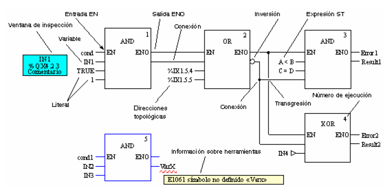
FBD programming language.
Ladder diagram. (LD)
This is the most widely used graphical interface language, without a doubt, its name is due to its structural form similar to a staircase where two vertical rails run, between which there are several horizontal rails that contain logic.
The left rail is the one that receives the energy flow (input) that represents the voltage and passes the energy to the right rail that represents the ground (output). Its resemblance to the old relay controllers is undeniable and its reading always follows the same sequence; from left to right and top to bottom.
This language is based on the use of contacts and coils, both can be normally open (NO) or normally closed (NC), and depending on this, their value will be activated or deactivated.
| SYMBOL | NAME | Description |
| Normally open contact | Fires when there is a logical 1 in the element it represents. | |
| Normally closed contact | Fires when there is a logical 0 in the element it represents. | |
| Normally open coil | Triggered when the combination to its left results in a logical 1. | |
| Normally closed coil | Fires when the combination to its left results in a logical 0. |
Main elements of LD language.
In this language there is also the possibility of using blocks that perform a specific function, for example, timers, counters, delay blocks, Boolean logic, etc. This is undoubtedly the PLC programming language preferred by specialists in this area, since it bears great similarity to classic relay logic, and for any technician or engineer with knowledge of electronics and electricity it is very easy to understand this way of operating. write code.

Example of LD logic in Schneider Electric Control Expert software.
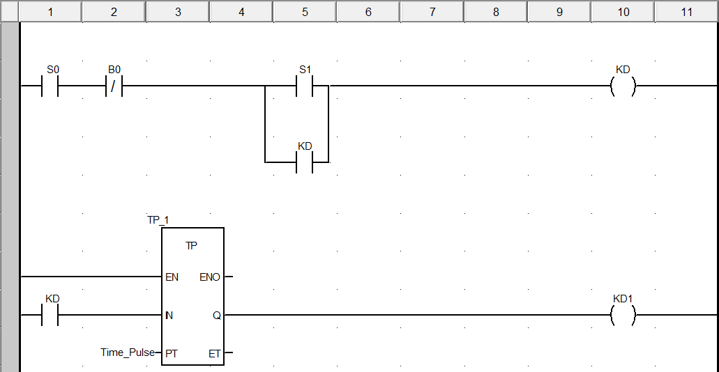
Example of LD logic in Schneider Electric Control Expert software.
If you think this article was useful to you, help us by sharing it, and maybe it could also be useful for someone else, leave us your comments about it and remember that we are very active on our Twitter, Instagram, LinkedIn and Facebook accounts. In addition, you can join our YouTube channel and be part of the Telegram community where we share all our content.
