Today we want to bring you an article in which we will be talking about Fritzing, a tool that many of our readers have been curious about after the publication of our Arduino Course, and where we present Fritzing as one of the softwares to use to work with our Hardware.
If you are not yet familiar with microcontrollers or specifically with Arduino, we invite you to visit our articles on the subject and we guarantee that you will understand everything perfectly.
Remember that you can leave us your opinion in the comments about this program and your experience if you have already used it.
Without further ado, let’s get started!
What is Fritzing?

Fritzing is nothing more than a “free” electronic design automation program (we’ll explain this at the end), designed to help designers and artists transition from prototypes (using, for example, test boards) to final products. Fritzing was created based on the principles of Processing1 and Arduino, allowing designers, artists, researchers and hobbyists to register their Arduino-based prototypes and create printed circuit diagrams for further fabrication. It also has a companion website that can help share and discuss sketches and experiences and reduce manufacturing costs.
1Processing Principle is a programming system designed to help visual artists access the world of code-generated images. It is not only a programming language, but also provides a pleasant environment designed not to scare beginners. The working environment is clean and no unnecessary technical information will interfere with the ongoing design. The development interface is simple and generous, allowing for quick testing and experimentation without compromise. Because of these qualities, Processing has become in a few years the tool of choice for teaching graphic programming in art schools, and has become the favorite tool of countless artists involved in the creation of interactive works.
Fritzing User Interface(UI)
Next we will talk about the UI of this program and what we will find once we have it installed on our computer. In our case we will be using version 0.9.3 for 64 bits which you can download directly from our repository by clicking here.
Once Fritzing is opened, we find a quite simple and pleasant interface.
We have 5 main tabs one after the other and at the end the “Components” section, all of these we will be explaining below.
1. Home / Welcome Screen
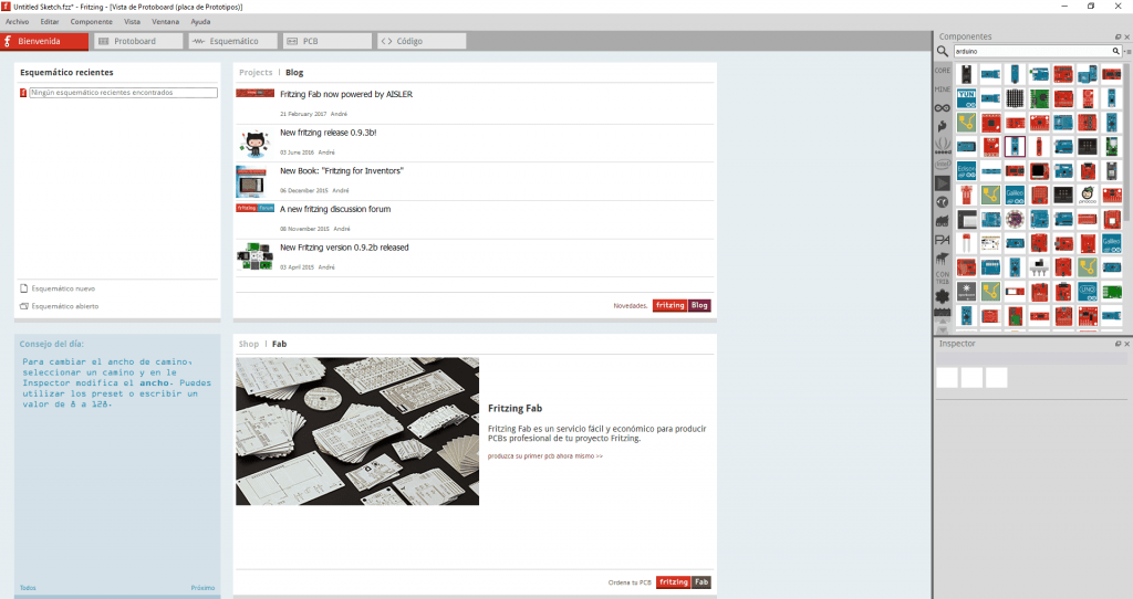
In this section, which we find when we open our program, basically shows us our recent projects in case we have done any. To the right we find the Blog section and news related to the platform: latest versions of the program, platform news, as well as some specific publications about Fritzing.
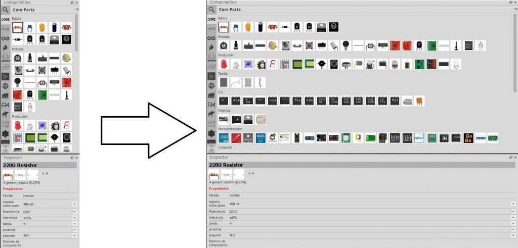
In the components section located on the right we can see the entire catalog of electronics that we can use in our projects. They are organized by different categories depending on their use and nomenclature. We can also use the search bar in this section, this gives us the facility of filtering depending on what we need to use.
Once you have selected the component(s) to be used in your project, just below the components you will find the Inspector section where you can see the specific characteristics of the selected instrumentation. It is very useful to use certain specificities such as giving an Ohms value to our resistor, modifying the value of our capacitor, or simply changing the color of the LEDs we use.
2. Breadboard
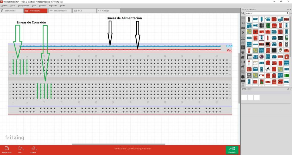
Once selected all our components we must place them on our test board or Breadboard to make our electrical connections.
For those who do not know what theBreadboards are used for, tell them that they are simply a board with holes electrically connected to each other, where the power lines follow a horizontal pattern. On the other hand the component connection lines follow a vertical pattern, this way we can make our connections in a logical and safe way, ensuring that our project works before making our PCB.
3. Schematic
To understand this section we must first understand the concept of schematic diagram in electronics.
The schematic diagram is usually related to the circuit. These diagrams are also called wiring diagrams or circuit diagrams and show how the different components of the circuit are connected. In these figures, the lines represent connecting wires, while other elements (such as resistors, lights and switches) are represented by standardized symbols called electrical schematic symbols.
We will now use a practical example in our Fritzing project to better illustrate our explanation. Remember to leave any questions you may have in the comments.
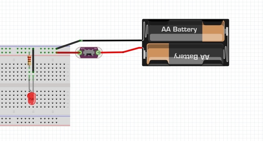
We can see that we selected some very basic components for our test circuit:
- Red LED: 1
- 220 ohm Resistor: 1
- Switch: 1
- Power Supply: 1
Basically with our circuit what we want is to turn on and off the LED with the switch we select. In this view with the Protoboard is where we make the basic connections to how it would look in real life. Next we will see how the schematic view would look like.
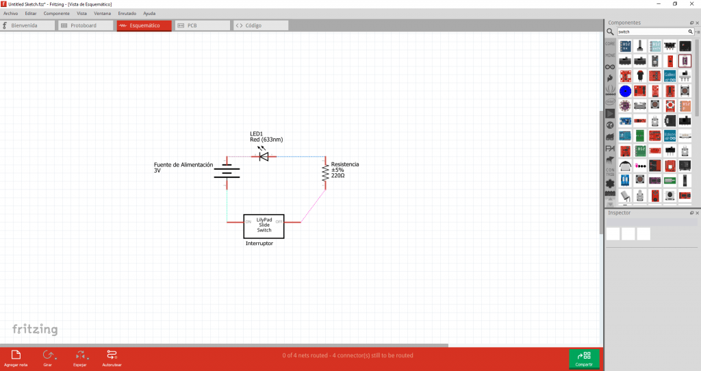
As you can see there is a very simple schematic connection diagram in which you can see the signaling of each of the elements used and their respective connection between them. In this way, once it is correctly connected, we can move on to make our PCB.
4. PCB
Printed Circuit Board (PCB) is a circuit whose components and conductors are contained in a mechanical structure. The conductive properties include copper traces, terminals, heat sinks or flat conductors. This mechanical structure is made of an insulating laminate between layers of conductive material. The overall structure is plated and covered with a layer of non-conductive resistance solder and a printed screen to place the legend of the electronic components.
Next we will see how the PCB model of our basic circuit would look like.
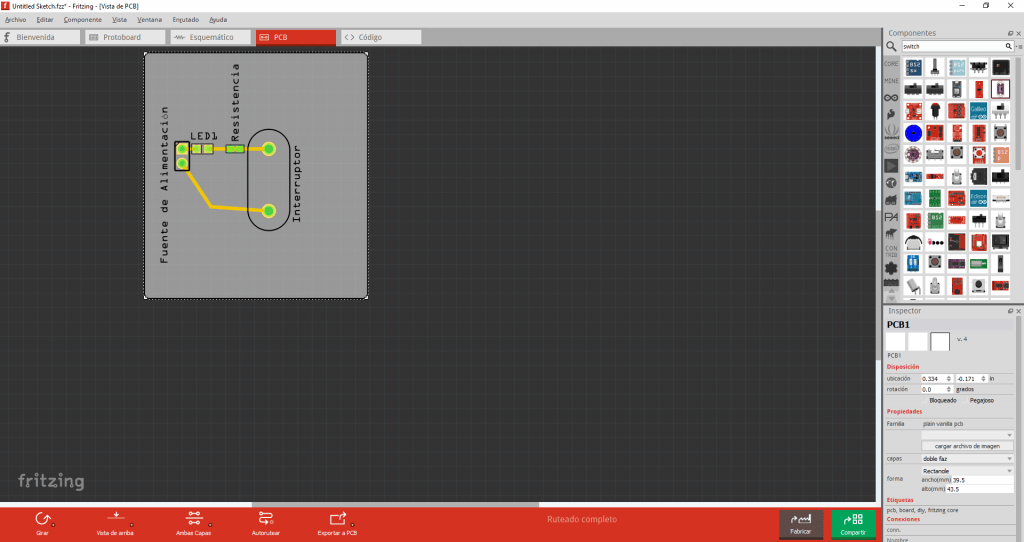
As you can see this would be our PCB design, which we can send to print directly from the program, with its respective cost. For the wiring and placement of our components on the PCB we must take into account certain rules, which correspond to the size, wires, temperature dissipation, etc..
If you would like to know more about this topic and would like us to make a specific article on PCB Wiring Rules, let us know in the comments.
5. Code
This last section is mainly dedicated to users who use Arduino boards in their electronics projects. In this section Fritzing will allow them to make the code they want to integrate it to the physical microcontroller they use. We emphasize physical because this program does not allow simulation in any of its features.
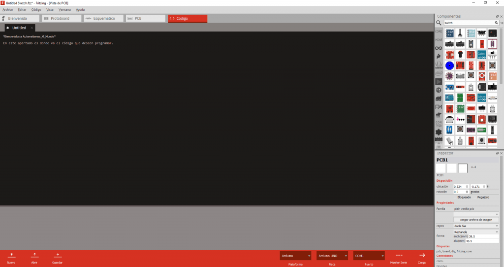
In this specific case, what users who wish to test their code have to do is to implement it on a real development board, with the possibility of implementing the code in the Fritzing console and uploading it directly to their microcontroller connected to the computer.
6. Download Fritzing(Important)
Although Fritzing is an open source software and supposedly “free”, it is no longer possible to download it from its website without making a donation.
In our Platform we have created a Repository where you can download it directly, without ads or third party links and completely free of charge.
Conclusions
We have been able to see all the potential that Fritzing offers us when it comes to our projects. Each of the segments that we were seeing in the article give us an idea of the extent to which we can use this program. From Automatismos_Xl_Mundo we do not consider this program to be the best in its category, but we highly recommend it for our beginners, although we no longer consider it as a free software.
In later articles we will be talking about other more advanced softwares that you can use for your electronics projects and you will have all the elements to choose the one that best suits your needs.
We hope you enjoyed the article. If so, please support us with a Like and share it on your social networks to reach more users.
Remember to join our community of Facebook where we are almost 1300 members. Follow us on our Instagram where we are constantly publishing exclusive content and you can tag us on Twitter if you have any questions or concerns.
